| Description of Technical Features |
| |
| The Trevisan Horizontal Machining Centres combine the advantages offered by a stationary-part machining with those of rotating-part machining. In-case of a rotating part in Vertical turning Lathe the Cutting speed is restricted due to the diameter of the chuck peripheral Speed. This result in not able utilizes the maximum cutting speed allowed. |
| |
| To achieve an optimized solution Trevisan Machines aredesigned with a Facing Head. The diameter of the Facing Head varies depending on the model. They are smaller for small diameter machining& bigger for bigger diameter Machining. So that higher RPM can be achieved to optimize the cutting. Also to achieve the above a specially designed Gear Box to generate an incredible Torque. Finally to deliver the power generated to the Tool, a genius Patent tool holder. |
| |
| Product Highlights |
| |
| The Facing Head |
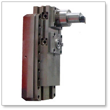 |
| TheFacing head is integrated into the headstock above the Main Spindle.The Position of the Facing Head is important in context of covering the diameter range. The Main Spindle slides inside the headstock, allowing the Facing head to rotate for its full range from Zero to Maximum diameter of its Model designed. The “U” axis travel varies for each Model. Please see the Technical sheet for details. The Facing diameter of the U axis slide is controlled by CNC command. The slide has more than one tool mounting positions from Model DS 450 for diameter flexibility this helps to cover the entire Range of the Diameters from minimum to Maximum diameters and Tools are loaded automatically from the tool magazine to one of thefirst or secondor thirdmounting positions. The Tool mounted on Facing Head can be used for single-point facing, boring, turning and threading operations. Standard tooling is employed at any programmed diameter to rough and finish complex internal and external profiles. Extra-large tools can be loaded automatically from a tool rack or spare pallet station, such as very long and heavy angle head attachments. The turning speed is fully programmable with constant surface speed control as on a conventional CNC lathe. |
| |
|
| Standard flood coolant comes from the nozzles at the top of the headstock, but as an extra option, coolant is supplied through the facing head and any of the tool holders directly to the tool insert, which greatly improves tool life and surface finish.Due to the growing demand of Surface Finish inside the bores under options is available “Coolant through Facing Head”. |
|
| |
| Standard Spindle |
 |
| The Main Spindlesuitable for milling, drilling, reaming and tapping operations. The Spindle protrudes enough as shown above after the facing Head reaches its home position.This spindle is driven by the high torque motor which is also used to control the indexing of any head attachments. |
| |
| Available under options a built in “U” axis drive to control the diameter of any smaller contour heads loaded from the tool changer. This function enables the machine to perform smaller single point turning, boring and threading operations, as well as the standard machining centre functions. |
| |
| In specific models RAM movement i.e. W axis can be supplied. |
| |
| Coolant is supplied through this ram head and any of the tool holders directly to the tool insert. |
|
|
| |
| Headstock & Gear Box |
| The Headstock carries the Facing Head& its spindle, the main Spindle & Gear Box. The Headstock also carries Spindle motor powered depending on the Model. The Optional Gear Box has Ratio designed to give maximum Power of Motor &achieves incredibly high Torque at the cutting point. The Gear train is such it is made available to either of the two uniquely different spindles. The motor & Gear box are mounted directly to deliver the power without any slip. |
| |
| The headstock travels up and down the middle of the column on re- circulating crossed roller bearings along the precision ground Y axis linear ways, being driven by computer controlled AC servo motor and precision ballscrew mechanism. This vertical movement of the headstock is also hydraulically counterbalanced. |
| |
| Machine Base |
| The base of the machine consists of a stress-relieved welded steel structure, engineered to maximize rigidity while incorporating open areas for efficient chip and coolant flow away from the working environment. The column travels along the top of this machine base on re-circulating crossed roller bearings along the precision ground linear ways, driven by the CNC controlled AC servo motor and precision balls-crew mechanism. The standard feedback system is by servo motor pulse coder, with the option of employing Heidenhain linear glass scales for even higher accuracy and repeatability. |
| |
| Column |
| The column consists of a stress- relieved welded steel structure, which is fed laterally on re-circulating crossed roller bearings along the precision ground linear ways by the computer controlled AC servo motors. The standard feedback system for this Z axisis by Heidenhain encoder mounted at the end of the balls-crew, with the option of employing Heidenhain linear glass scales for even higher accuracy and repeatability. |
| |
| Column Mounted Tool Changer and Magazine |
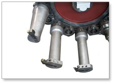 |
| This tool changer and tool magazine are mounted on the side of the column thus enabling tool changes to be performed at any position along the X axis. The tools are exchanged automatically by means of the two hand hydraulic manipulator. The TG2000 tool holder system was specially developed by GT Trevisan and has a unique patent. Any previous tool is removed and stored into whichever magazine it came from, after which a tool automatically selected from the magazine is moved to either of the two high torque head positions or to the ram spindle. The magazine will always take the shortest path to find the next tool, and searching can be performed during machining operations. A TG2000 tool holder base is supplied as standard for each magazine position. Extended magazine tool capacity can be supplied on request. As a standard TG 2000 tool holders will be supplied equal to the number of Magazine capacity selected. |
|
|
| |
| Rotary Table |
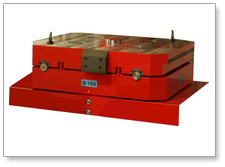 |
| The rotary table consists of a Meehanite cast iron structure housing a 360 degree rotary system with a hydraulic locking function. The table can be rotated by electronic hand-wheel or CNC command to any indexing position or programmed to move continuously at a specified speed in either direction. The rotary movement is powered by a brushless AC servo motor and accuracy and repeatability of this B axis movement is guaranteed by the Heidenhain rotary encoder feedback system. The rotary table travels along the top of a rotary table base on re-circulating crossed roller bearings along the precision ground X axis linear ways, driven by the CNC controlled AC servo motor and precision ball-screw mechanism. The standard feedback system is by Heidenhain encoder mounted on the end of the ball-screw, with the option of employing a Heidenhain linear glass scale feedback system for even higher accuracy and repeatability. The standard rotary table is enhanced with a twin pallet changer system, but this can be modified to automatically receive pallets from a variety of pallet changer options, including complete flexible manufacturing systems. |
|
|
| |
| Pallet Change System |
| To perform a pallet change the 'X' axis is automatically moved to a reference position, after which a pallet rolls forward along linear rails to position over the rotary table. The pallet is then hydraulically clamped to the rotary table and a hydraulic motor retracts the push and pull drive chain mechanism. When work is complete on the first pallet, it is returned to the pallet station it came from, after which the 'X' axis moves the rotary table to the second reference position ready for the other pallet to be loaded. The pallet changer is powered by 'M' function controlled hydraulic motors and chains, together with position sensors and hydraulic clamping mechanisms. |
| |
| Electrical System |
| The cabinet containing the electrical and electronic system is independent from the machine and connections are established by means of a heavy duty overhead ducting system. The interface between the CNC control and the Trevisan machine has been specially engineered by system by Trevisan Macchine Utensili S.p.A.. |
| |
| Hydraulic System |
| The hydraulic system consists of a variable displacement pump mounted on the hydraulic tank and high pressure oil is directed by means of hydraulic valves to facilitate tool unclamping, chucking, indexing, and also to power the “Y” Axis counter balance system. |
| |
| Automatic Lubrication System |
| The central lubrication system feeds oil to all machine slide-ways, ball-screws and bearings at a rate and interval specified by control parameter and is monitored for system failure and low oil level. |
| |
| High Pressure Coolant System ( 16 bar ) |
| The coolant is pumped from the coolant reservoir through a filtration system and various heavy duty pipes to the two spindles and distributed through the centre of the ram and through various coolant nozzles at the top of the integrated turning and boring spindle. The system includes a set of safety shields and Trevisan recommends the customers, that a trough with a top grill is installed, at site by the customer, around the machine to collect and return the coolant |
| |